


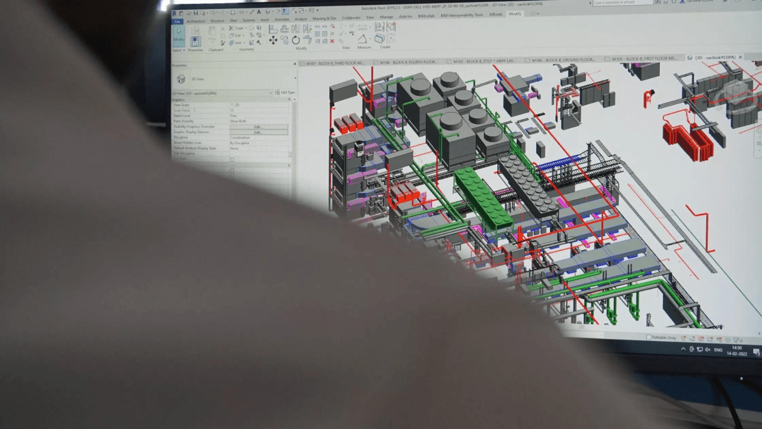
In the modern construction industry, Building Information Modeling (BIM) has become indispensable for designing and managing complex projects, especially in Mechanical, Electrical, and Plumbing (MEP) systems. At Desapex, our adoption of BIM for MEP design has not only streamlined our processes but also enhanced the quality and efficiency of the systems we deliver. This Newsletter delves into the detailed steps we follow using Autodesk Revit and Solibri, highlighting how these tools facilitate superior MEP system design for commercial buildings, workplaces, and data centers.
Introduction to BIM in MEP Design
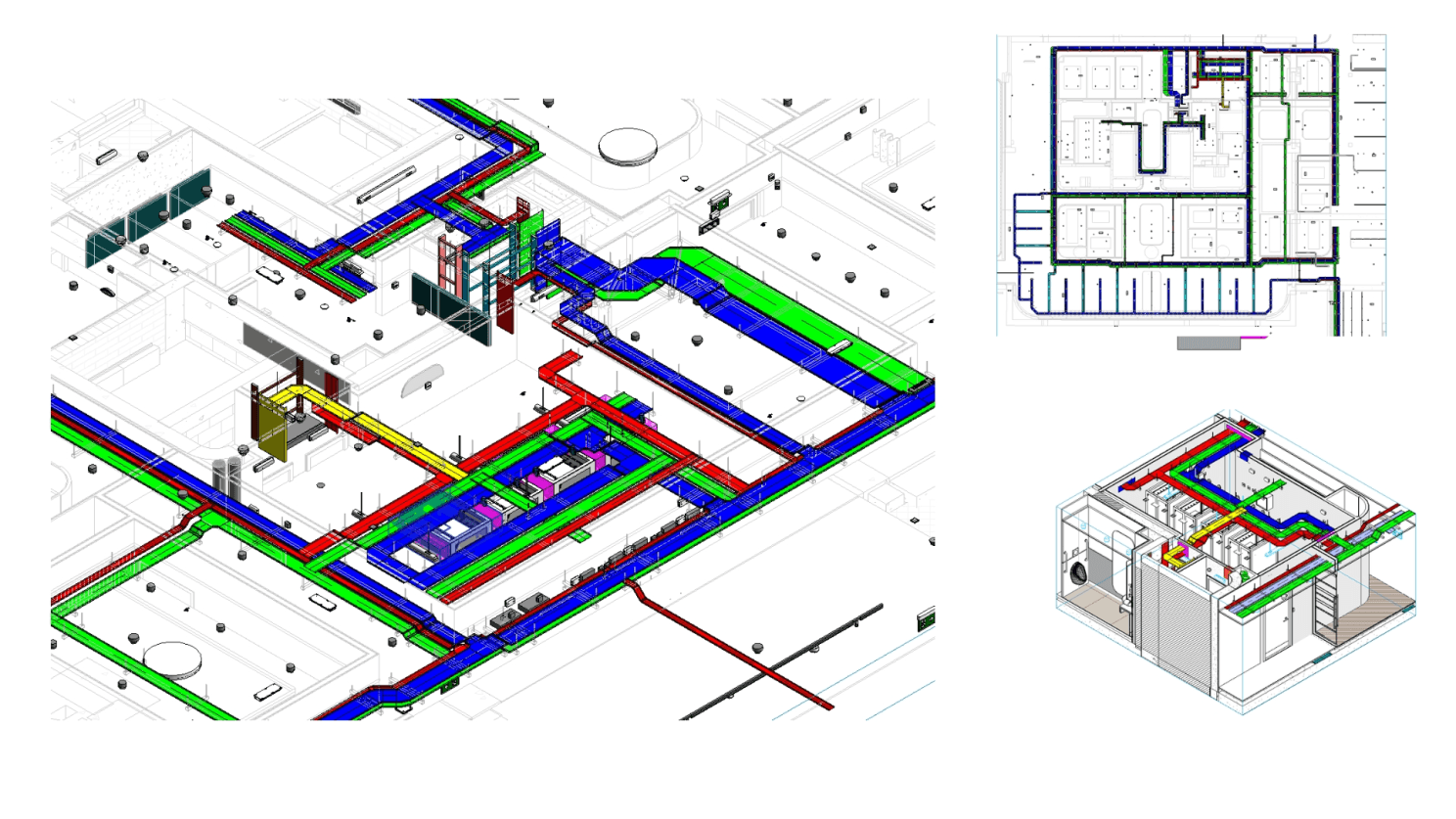
BIM represents a paradigm shift in how construction projects are designed, coordinated, and executed. In MEP design, BIM allows for the creation of highly detailed and integrated models that include all mechanical, electrical, plumbing, and fire protection (MEPF) systems. These models serve as a comprehensive digital twin of the physical building, providing a clear, visual representation that can be used throughout the project lifecycle.
Why Autodesk Revit for MEP Design?
Autodesk Revit stands out as one of the most powerful BIM tools for MEP design. Its ability to integrate mechanical, electrical, and plumbing systems into a single, cohesive model makes it a preferred choice at Desapex. Revit’s capabilities extend beyond simple 3D modeling; it allows for detailed analysis, simulation, and coordination, ensuring that all MEP systems are designed with precision and efficiency.
Detailed Workflow Using Autodesk Revit for MEP System Design
1. Mechanical System Design
Step 1: Creating the HVAC System Layout Using Revit, we start by laying out the Heating, Ventilation, and Air Conditioning (HVAC) system. Revit’s parametric modeling capabilities allow us to easily place components like air handling units (AHUs), ducts, vents, and diffusers. The software’s drag-and-drop functionality simplifies the placement of these elements while ensuring they are connected seamlessly.
Step 2: Ductwork Design and Routing Revit’s automated routing tools are particularly beneficial for designing ductwork. We can define the airflow requirements for each space, and Revit automatically sizes the ducts and generates the most efficient routing paths. This feature not only saves time but also ensures optimal airflow, reducing the need for manual calculations.
Step 3: Energy Analysis and Load Calculations One of Revit’s most powerful features is its ability to perform energy analysis directly within the model. By inputting building-specific parameters like occupancy, location, and materials, we can simulate the HVAC system’s performance under different conditions. This analysis helps us optimize the design for energy efficiency, ensuring that the system meets both the client’s requirements and relevant standards like ASHRAE 90.1.
Step 4: Coordination with Architectural and Structural Models Revit allows us to overlay the HVAC system model with architectural and structural models. This integration is crucial for ensuring that the mechanical components do not interfere with the building’s structure or other systems. For example, we can detect and resolve issues such as ducts passing through structural beams, avoiding costly changes during construction.
2. Electrical System Design
Step 1: Electrical Layout and Circuiting In Revit, we begin the electrical system design by creating layouts for lighting, power distribution, and communication systems. The software allows us to easily draw circuits, connect fixtures to power sources, and define circuit parameters such as voltage and current. The visual nature of Revit’s interface makes it easier to see the relationships between different components and ensure that all connections are correct.
Step 2: Cable Tray and Conduit Routing Routing cable trays and conduits is a critical part of electrical system design. Revit’s automated tools help us define the most efficient paths for these elements, taking into account space constraints and potential clashes with other systems. The software also ensures that all conduits and cable trays are sized correctly, which is essential for maintaining system performance and safety.
Step 3: Load Calculations and Panel Schedules Revit enables us to perform detailed load calculations based on the electrical components in the model. The software generates panel schedules automatically, which include information about circuit breakers, feeder sizes, and load distribution. This feature is particularly useful in ensuring compliance with standards such as the National Electrical Code (NEC) and helps in preparing accurate documentation for contractors.
Step 4: Coordination with Other MEP Systems Revit’s coordination capabilities are invaluable when integrating the electrical system with mechanical and plumbing systems. By overlaying the models, we can detect potential conflicts, such as a cable tray intersecting with a duct or a conduit running through a plumbing pipe. Resolving these issues in the design phase prevents costly rework during construction.
3. Plumbing System Design
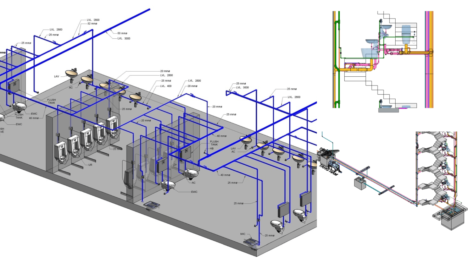
Step 1: Plumbing Fixture Placement The plumbing system design in Revit starts with placing fixtures such as sinks, toilets, and water heaters. The software’s extensive library of plumbing components allows us to select the appropriate fixtures for each space, ensuring that they meet both the client’s needs and local plumbing codes.
Step 2: Piping Design and Routing Revit’s automated routing tools make piping design efficient and accurate. We define the flow rates and pressures required for each fixture, and Revit generates the most efficient piping routes. The software also calculates pipe sizes and material requirements, ensuring that the system is both cost-effective and compliant with standards like the Uniform Plumbing Code (UPC).
Step 3: Pressure and Flow Analysis Revit includes tools for analyzing the pressure and flow characteristics of the plumbing system. By simulating different usage scenarios, we can optimize the system to ensure consistent water pressure and flow rates throughout the building. This analysis is crucial in preventing issues like water hammer and ensuring that the system operates efficiently under peak demand.
Step 4: Clash Detection and Coordination As with mechanical and electrical systems, coordinating the plumbing system with other MEP systems is essential. Revit allows us to identify and resolve potential clashes, such as pipes intersecting with electrical conduits or ducts. This coordination ensures that all systems can be installed without interference, reducing the risk of delays and rework on-site.
Clash Detection and Coordination with Solibri
While Autodesk Revit is powerful for modeling and analysis, Solibri complements it by providing advanced clash detection and coordination capabilities. At Desapex, we use Solibri to thoroughly review our BIM models before construction begins.
Step 1: Importing the Revit Model into Solibri The first step in the clash detection process is importing the Revit model into Solibri. Solibri’s advanced algorithms analyze the model for clashes between different building elements, including MEP systems, structural components, and architectural features.
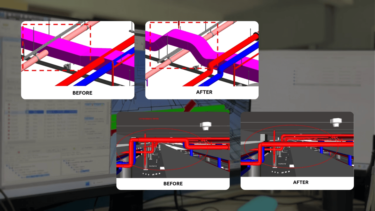
Step 2: Identifying and Prioritizing Clashes Solibri not only detects clashes but also categorizes them based on severity and impact. For example, a clash between a structural beam and a major duct might be prioritized over a minor clash between a conduit and a ceiling tile. This prioritization helps us focus on resolving the most critical issues first, ensuring that the project stays on track.
Step 3: Collaborative Issue Resolution Solibri’s issue management tools allow us to collaborate with other stakeholders, such as architects and contractors, to resolve clashes. The software provides detailed reports that include visualizations of the clashes, making it easier to understand the issues and propose solutions. This collaborative approach ensures that all stakeholders are aligned and that the necessary changes are made before construction begins.
Step 4: Iterative Review and Approval After resolving the initial set of clashes, we re-import the updated Revit model into Solibri for another round of checks. This iterative process continues until all clashes are resolved, and the model is approved for construction. This rigorous approach minimizes the risk of unexpected issues on-site and ensures that the MEP systems are installed as designed.
Compliance with Industry Standards
At Desapex, we prioritize compliance with industry standards to ensure that our MEP designs meet or exceed client expectations. Our processes are aligned with:
ASHRAE Standards: For HVAC systems, we follow ASHRAE standards to ensure optimal energy efficiency and indoor air quality.
National Electrical Code (NEC): Our electrical designs comply with the NEC, ensuring safety and reliability.
Uniform Plumbing Code (UPC): We adhere to the UPC for all plumbing designs, ensuring compliance with local and national regulations.
ISO 19650: For BIM implementation, we follow ISO 19650 standards, ensuring consistent information management across all project phases.
The Future of MEP Design at Desapex
BIM-based MEP design has transformed how we approach projects at Desapex. By integrating Autodesk Revit and Solibri into our workflow, we’ve been able to deliver MEP systems that are not only highly efficient but also aligned with the highest industry standards. The detailed design process, from HVAC layout to clash detection, ensures that our projects are executed with precision and minimal risk.
As we continue to innovate and expand our capabilities, we’re excited about the future of BIM in MEP design. Whether it’s a commercial building, a workplace, or a data center, we’re committed to pushing the boundaries of what’s possible, delivering systems that are not only functional but also sustainable and cost-effective.
At Desapex, the future of MEP design is digital, collaborative, and efficient—and we’re proud to be leading the charge.